Electronics design
Assignment
This week's assignment is "redraw the echo hello-world board, add a button and LED check the design rules, and make it"
Files
Here's a zip-folder with my rml-files, ready for the roland mill
helloEcho .png trace and cut-out
Selected software for circuit board design
For this week assignment I worked with the following software:
- Eagle: Eagle
- Adope Capture CC (Free app for iPhone): Adope Capture CC
- InkScape: InkScape
- Fab Modules: Fab Modules
Eagle
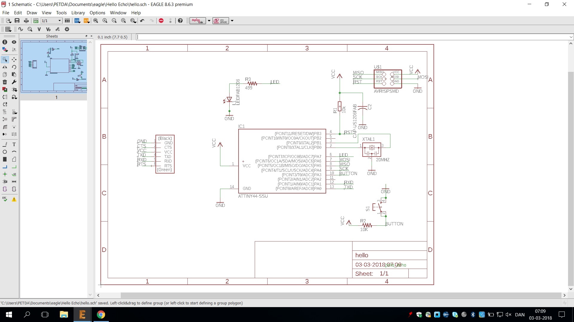
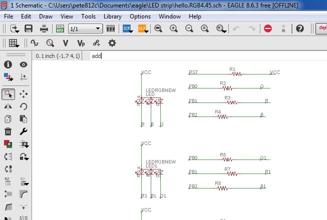
I started this week out with installing Eagle and imported a parts library from the FabAcademy schedule page for this week fab.lbr I started schematic design (.sch) with EAGLE and added following components:
-ATtiny44-SSU * 1
-AVRISPSMD * 1
-CAP-US1206FAB * 1
-6MM_SWITCH6MM_SWITCH * 1
-FTDI-SMD-HEADER * 1
-RESONATOR * 1
-RES-US1206FAB * 3
-LEDCHIP-LED0805 * 1
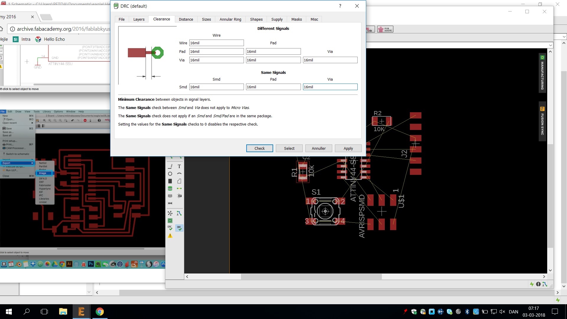
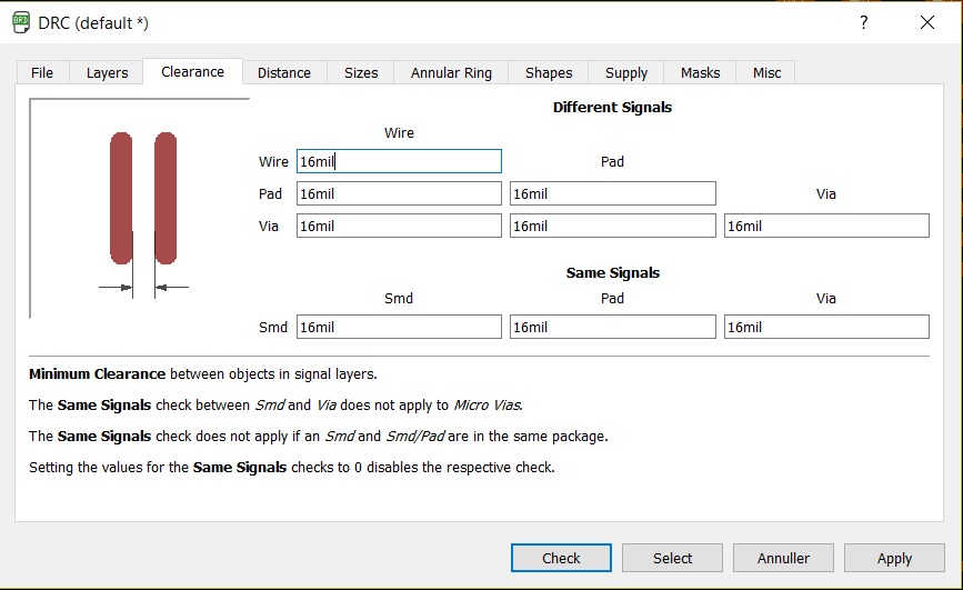
Then I connected each parts using "wire", "label" and "define name/value". After that, I clicked GENERATE board for designing the board and connected each parts using "route". Here I found out after several attempts an important settings when drawing circuit boards with the specifications of the milling machine. I had to choose millimeters under grid and make the route 0,4064 mm. and under DRC all values in the clearance and supply tab should be set to 16 mill and the maximum width in the sizes tab should be set to 16 mill cf. my picture below.
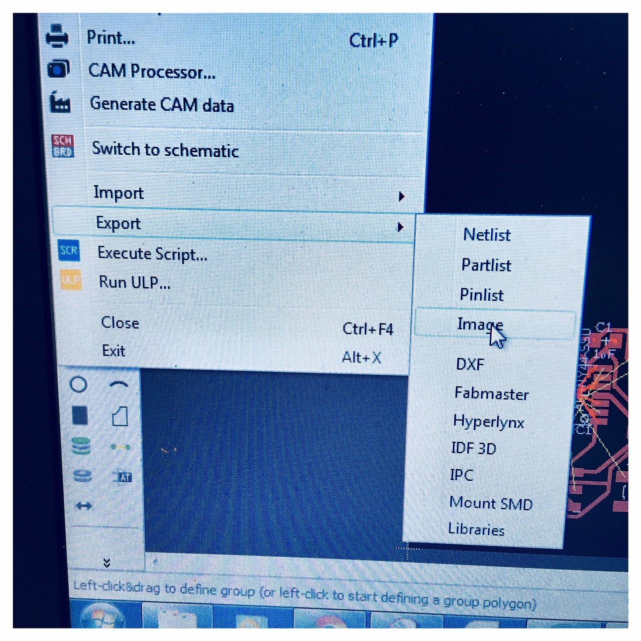
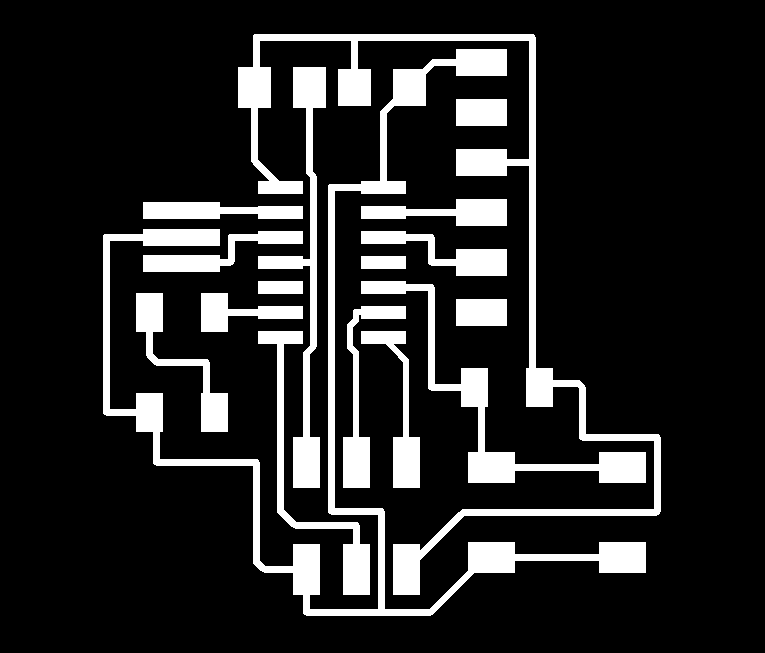
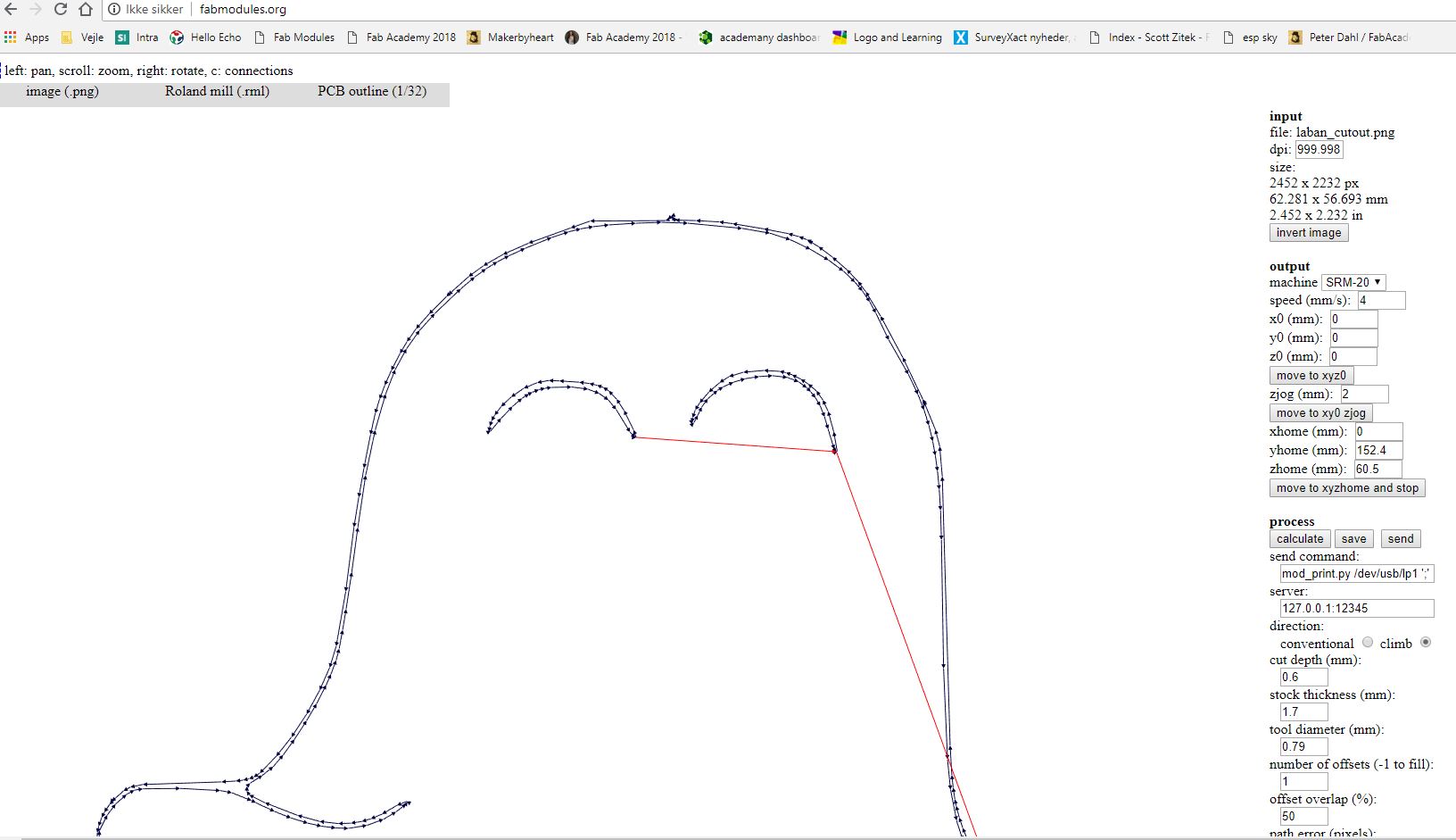
Then I exported the board design both traces and dimensions as monochrome image (.png). as described in the tutorialsite under Eagle. For creating the milling path I used www.fabmodules.org as with the ISP in week5. The toolbits we all used in Fablab Spinderihallerne for our Roland Monofab srm-20 and these milling projects are the 1/64 for milling traces and the 1/32 for milling the outline.
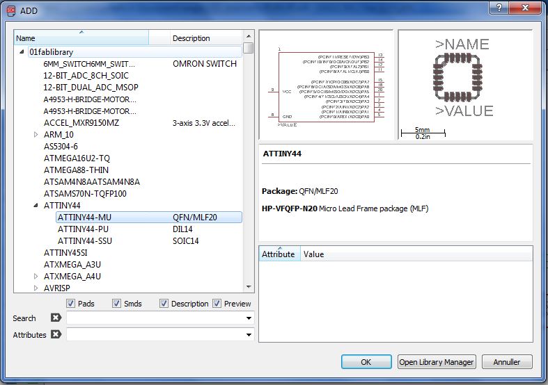
After adding the fab.libraries (file attached in the top of the page) I could easy add the components for the Fablab-inventory list into my Eagle schematics and boards. I used the following steps. Write add and press enter in the shearch bar and click on the fab.lib-folder, then choose which component you want to import and click OK. See the steps in the pictures below.
A couple of important settings when drawing circuit boards with the specifications of the Roland milling machine we have in our lab, is to choose millimeters under grid and make the route 0,4064 mm. Under DRC all values in the clearance and supply tab should be set to 16 mm and the maximum width in the sizes tab should be set to 16 mm.
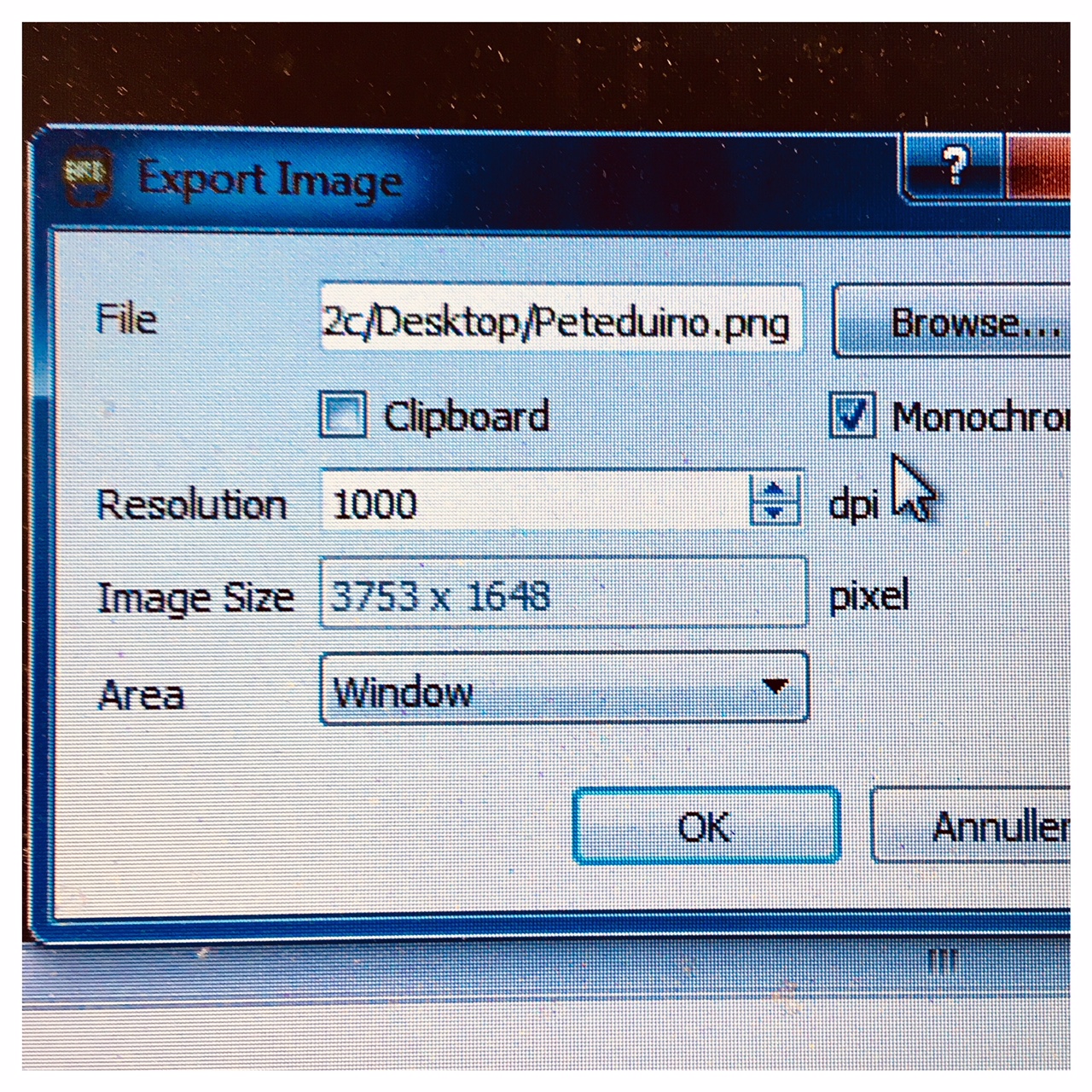
When I came to the issue of exporting the circuit I had made I vent to tools and layer settings to only select the top layer and pads. When exporting the image as an .png-file I selected monochrome and a 1000 dpi as suggested by our Fab Academy instructor.
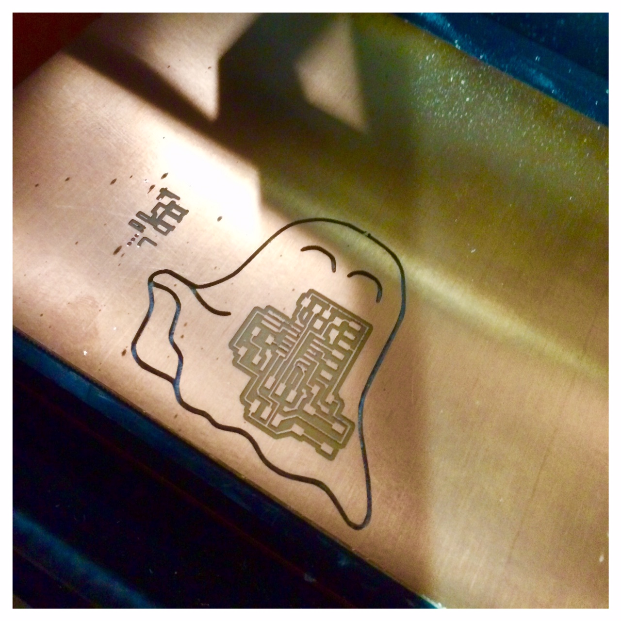
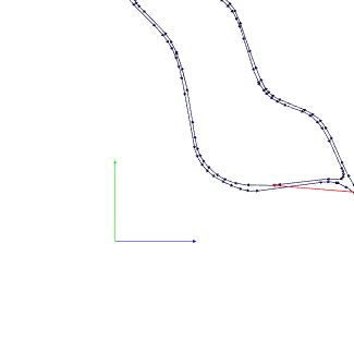
I made some different mistakes the first time I was milling with the Roland as you can see at the picture of my first ghost with lines running outside the cut-out.
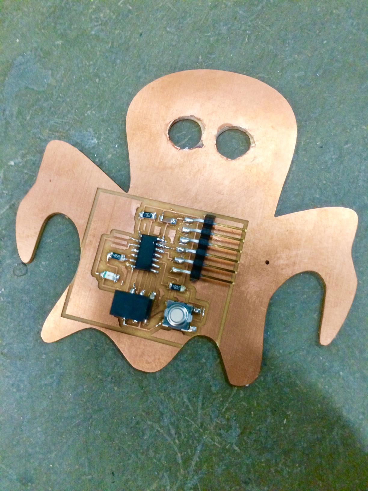
I cut the traces including a frame that made the ghost look a bit ugly, with the line goes beyond the actual cut-out. Not that it broke the circuit itself, but it did not look nice. The first ghost I had drawn was also quite large in order to contain the traces.
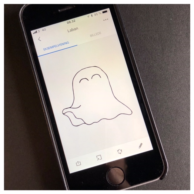
Handdrawing
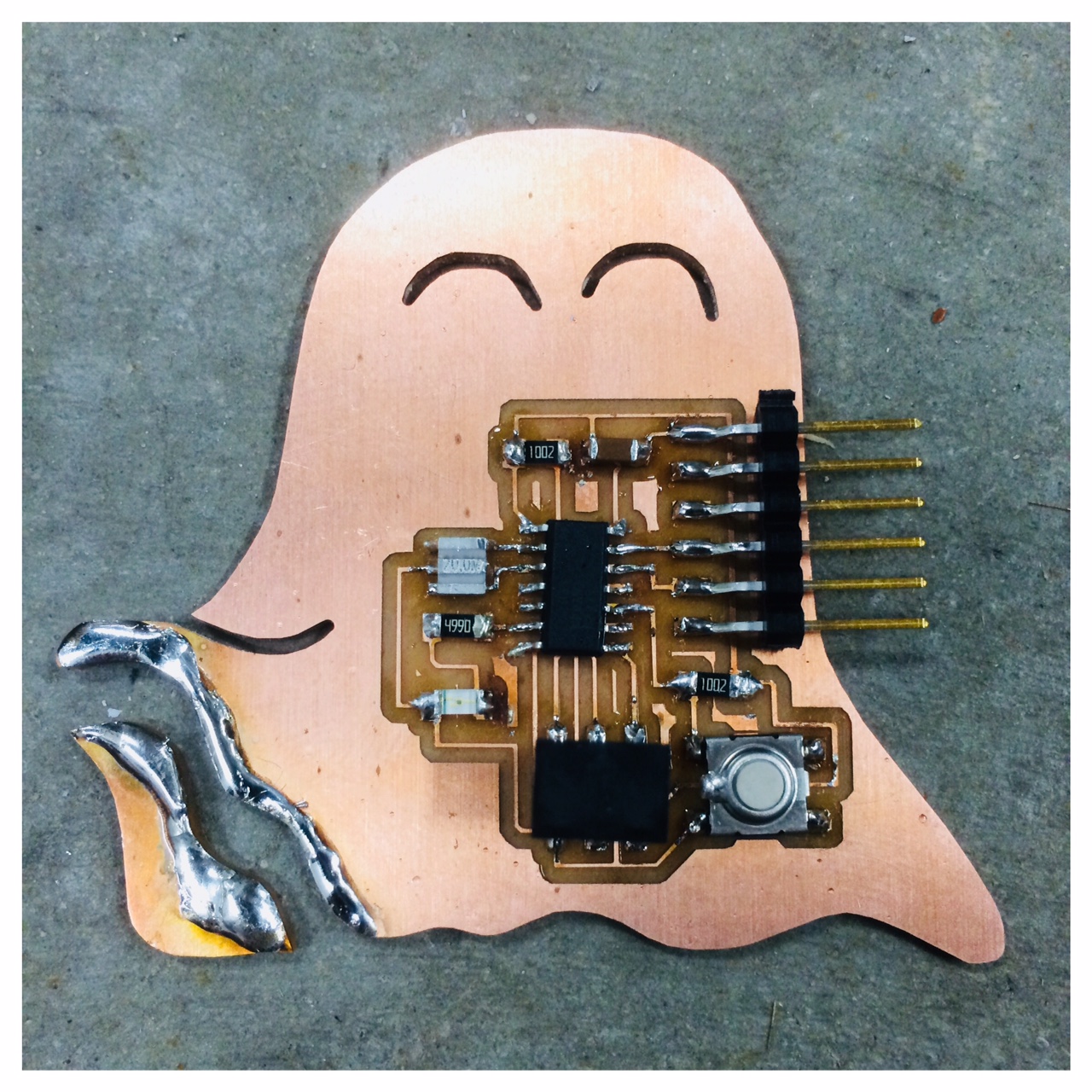
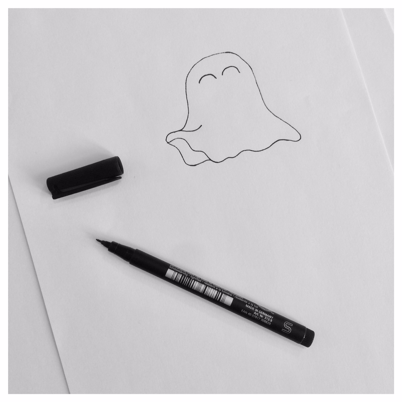
I therefore drew a new ghost by my hand. A shape that suited the shape of the traces better and added a few details such as eyes. I then scanned the drawing into InkScape and resized/cropped it so that it became perfect for my little ghost.

Adope Capture CC
To scan my handdrawing I would use as a cut-out I used Adope Capture. This is a free app that allows you to "clean" and edit your photos as well as make some really nice black and white contrast images from your photos (it's the same app I've used for editing the files my icons on the website).
Adobe Capture CC gives you the the option to create production-ready color themes, patterns, vector-based shapes, 3D materials, type, and custom brushes—all from a single photo. It's a really great app, that I think make the process from going to drawing to digital image easy.
Inkscape
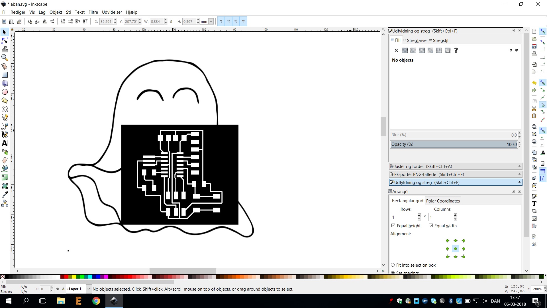
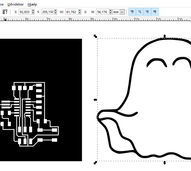
To avoid the same mistake I made with my first ghost, where my trace went outside the cut-out, I imported my drawing to InkScape to make sure that both images had the same height and width, and that the trace was located correctly in relation to the cut-out.
It's a bit cumbersome and there are probably easier ways to do it than the way I do it. But I import my trace (the monocrome png from Eagle) to InkScape and my silhouette of a ghost I wanted to function as the cut-out or interior. Then I make sure that the ghost get an appropriate size so that it can contain my entire eagle trace inside, with enough room, so that the cut-out do not interfere with the traces (as the mistake I made on my first ghost, check the image in the top of this site).
Aligning the Ghost
Now it is very important to align the two pictures so that the they have the same starting point, otherwise the milling machine will possibly start in two different locations, so your cut-out can cou lines through your traces. For making sure that this would not happen I use InkScape. I start out making sure that the trace fits inside the cut-out. If not I make my cut-out picture bigger (important: do not change the traces, this picture has to stay the same size, otherwise the traces would no longer fit the components you are soldering on later in the proces).
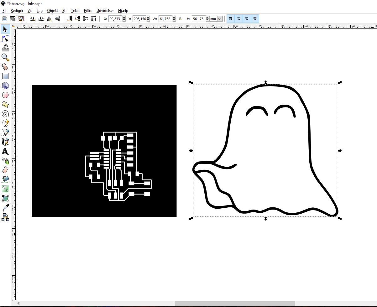
When you have the right size of the picture, make sure that the pictures have the same frame size. You can crop the pictures in InkScape by using the Rectangle tool and draw out an area you’d like to keep. Now use the Selection tool to select the image and rectangle, then head up to Object > Clip > Set. This is how you can do cropping using Inkscape, making sure your picture are the right and same size. I always dubble check the picture size by checking the top toolbar about height and width.
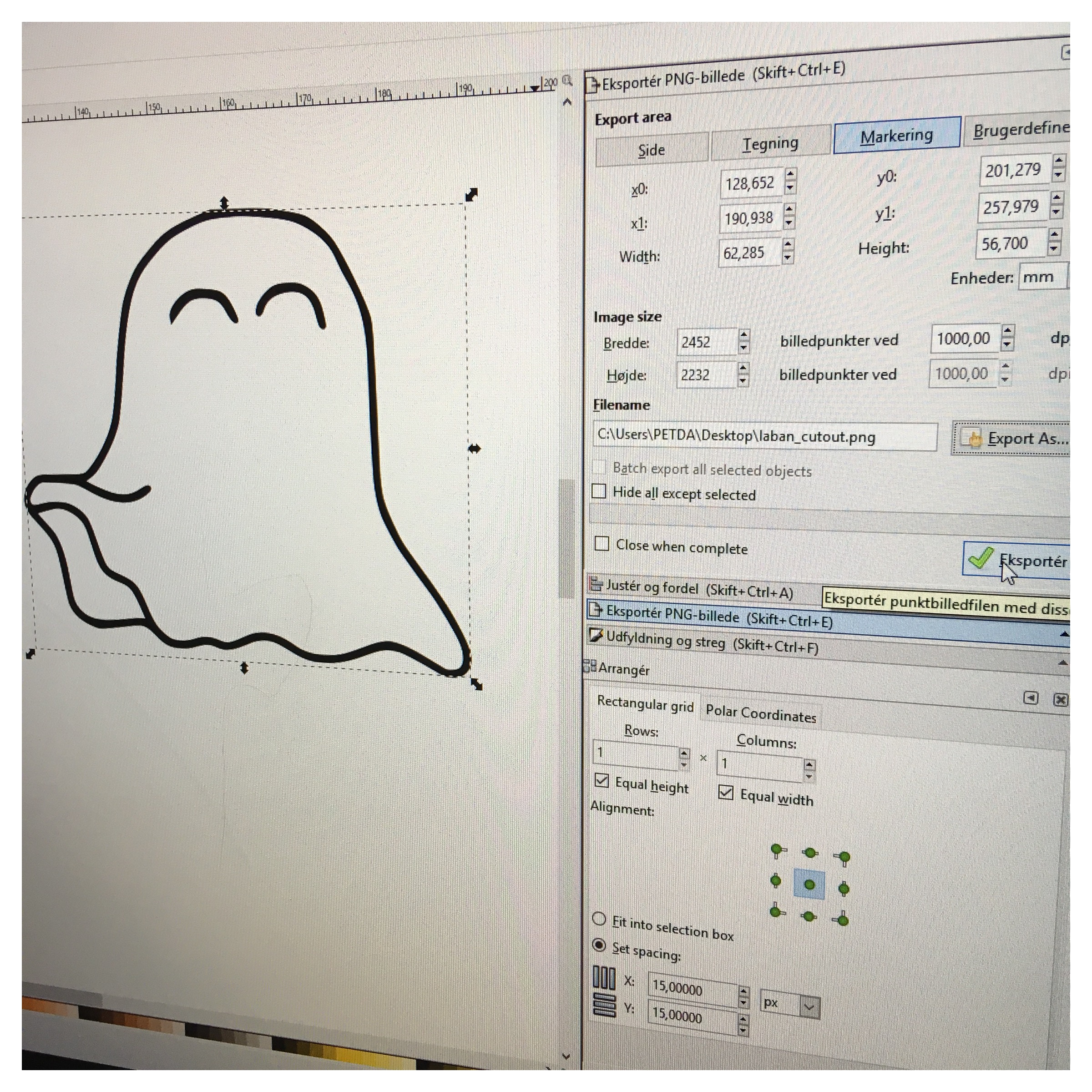
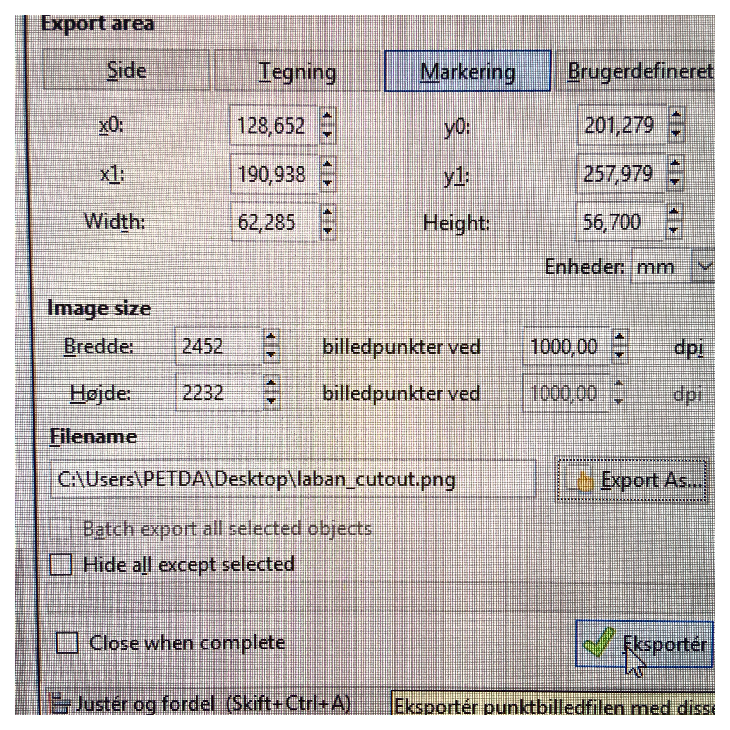
When I export the PNG form Inkscape I choose to export it with a 1000 dpi. This has worked grat for me when using Fab Modules later on in the process.
Fab Modules
The fab modules provide a set of software tools for personal fabrication, intended for use with machines in our fab labs. You can use it for It Tools to design 2D and 3D objects, Functions to generate 2D and 3D toolpaths. I used Fab Modules for milling all my Traces and Cut-outs on our Roland SRM-20 CNC.
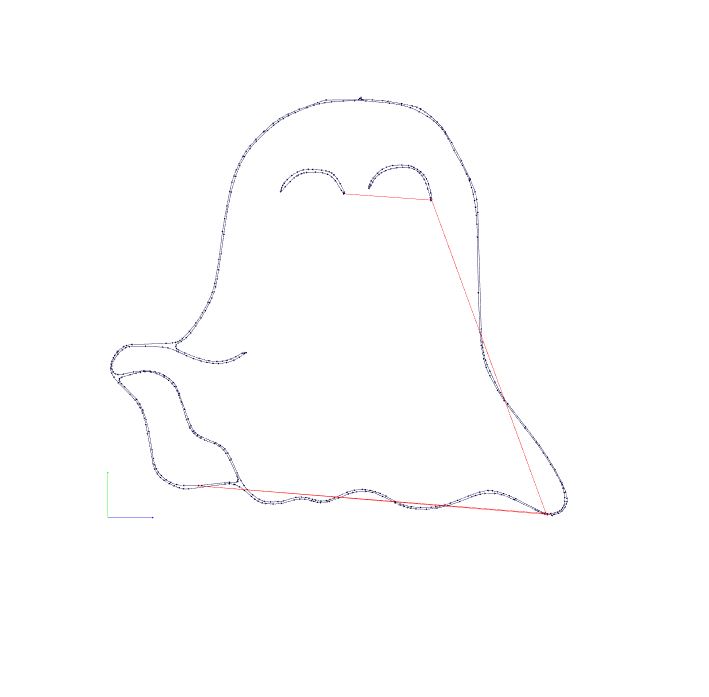
By making sure the pictures frame are the same size, you can see that it create a start point or an angle in the corner of the picture of the ghost. This results in having the opportunity to start the Roland CNC from the same starting point when I mill the two toolpaths'. My trace and my cut-out.
I wanted to make a funny "cut-out" for my Hello Echo board, because I think this could be a really great assignmet for kids to work with, maybe for a creative badge. At the moment there are some public schools in Vejle (Denmark) who have bought and work with the Roland Monofab srm-20 in their labs, but they use it mostely for castforms. I think the possibility to make small PCB's is such a brilliant way of learning about circuits that kids today must not miss out. My next step is to plan a small course for kids at a school in Vejle called "Kirkebakkeskolen" where we are going to draw and make funne badges or brooch's out of PCB. For the moment I have some difficulties with arranging my traces with my cutout, and findeing a way of adding two LED's as eyes. I think if the eyes of my ghost are two RGB-LED's so the kids and I can programme the eyes to variete in color.