Electronics Production
Assignment
Make an in-circuit programmer by doing printed circuit board milling (PCB)
Files
Here is a zip folder with Brians and my FabISP files in .png, .rml and .svg
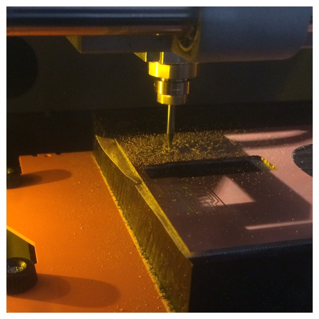
Learning to use Fabmodules & Roland SRM-20
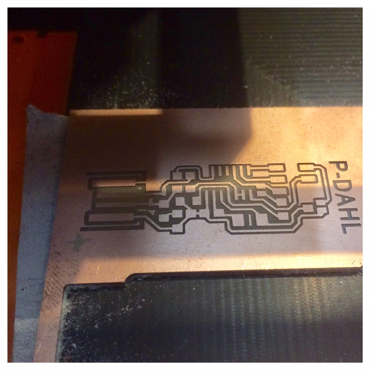
For preparring my PNG-files for our labs Roland SRM-20 mill I will use fabmodules.org. I went to Fabmodules webpage and imported my PNG-file of the trace and later the cut-out. I set the output for the Roland Mill (.rml). In process I choose at first my traces (and second time my cut-out, depending on what you want to do). PCB traces (1/64) and for the Cut-out PCB Outline (1/32). Then I had to choose the mashine in this case the SRM-20. For the output parameter section: Machine: SRM-20, and I keept the default speed (4mm/s) and changed the x0,y0,x0 (mm): for 0 instead of 10.So now it was time to calculete but I was having some troubles with my traces and the tool diameter messering 0,4 mm. In the calculation some traces was to close for the tool diameter and the traces disapeared because of the possibility to get milled away. I talked with our local Fab Academy instructor Lorenzo and decided to mill with the 0,4 mm tool, trying to cheat the maschine by saying the tool diameter was 0,3 mm. Now the traces apeared and I could mill the ISP and it looked nice. Just to be sure that the traces was in full function I measured it using the multimeter. I used the multimeters audio function, where it gives a little sound when there is a connection. I actually think it gives a good understanding of the circuits to check it with the multimeter, you have to sit and follow the traces closely.
Preparing the PCB for soldering
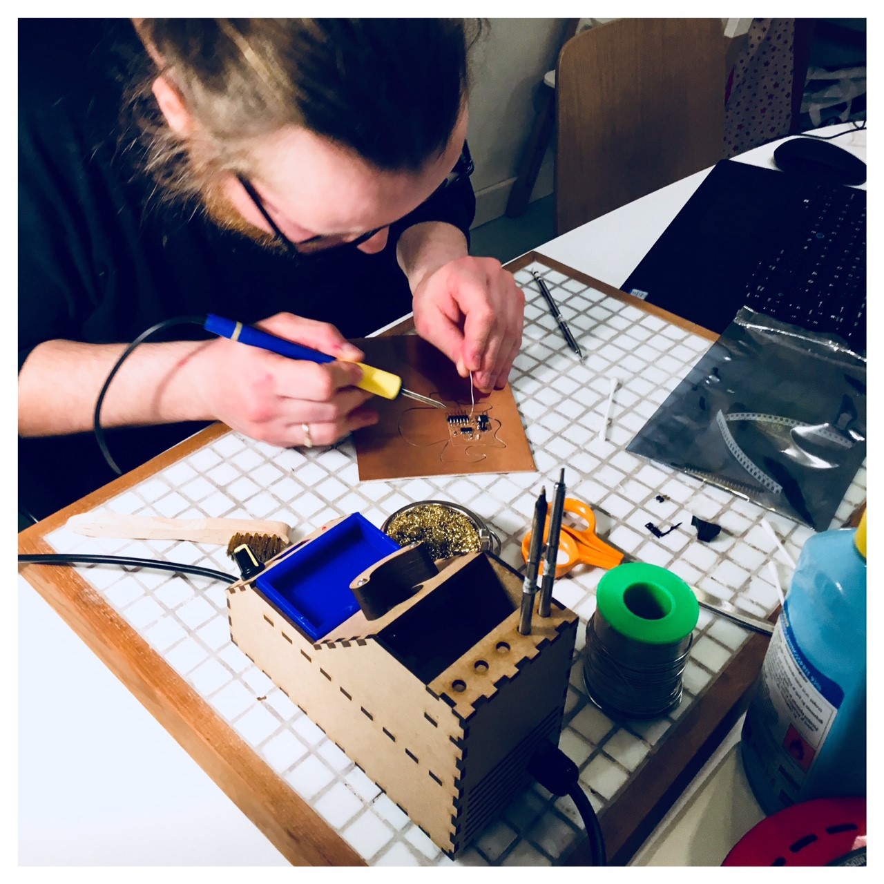
Before soldering I had to walk through some small steps to make the soldering easier for myself. The newly milled PCB needs to be well dusted of to get all the cut away material away. Then I washed the PCB in water and dish soap to ensure that all adhesive material was removed. At last I went through my PCB to check it for any unintentionally broken connections or small parts that hasn't caught my eye.Components
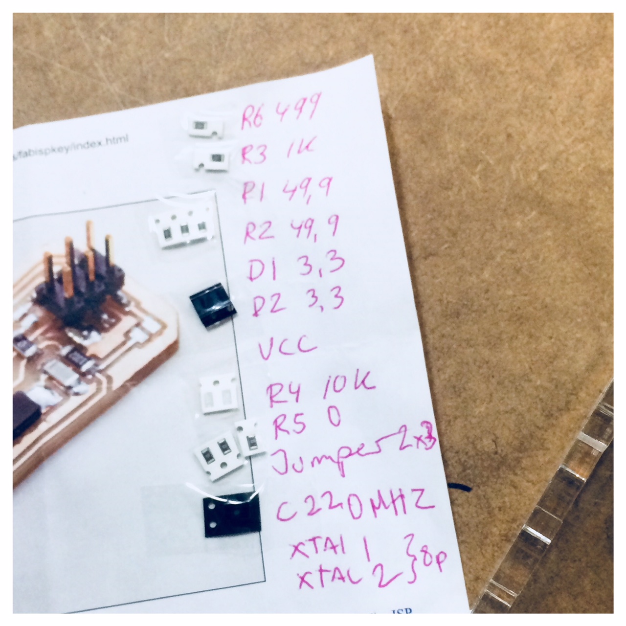
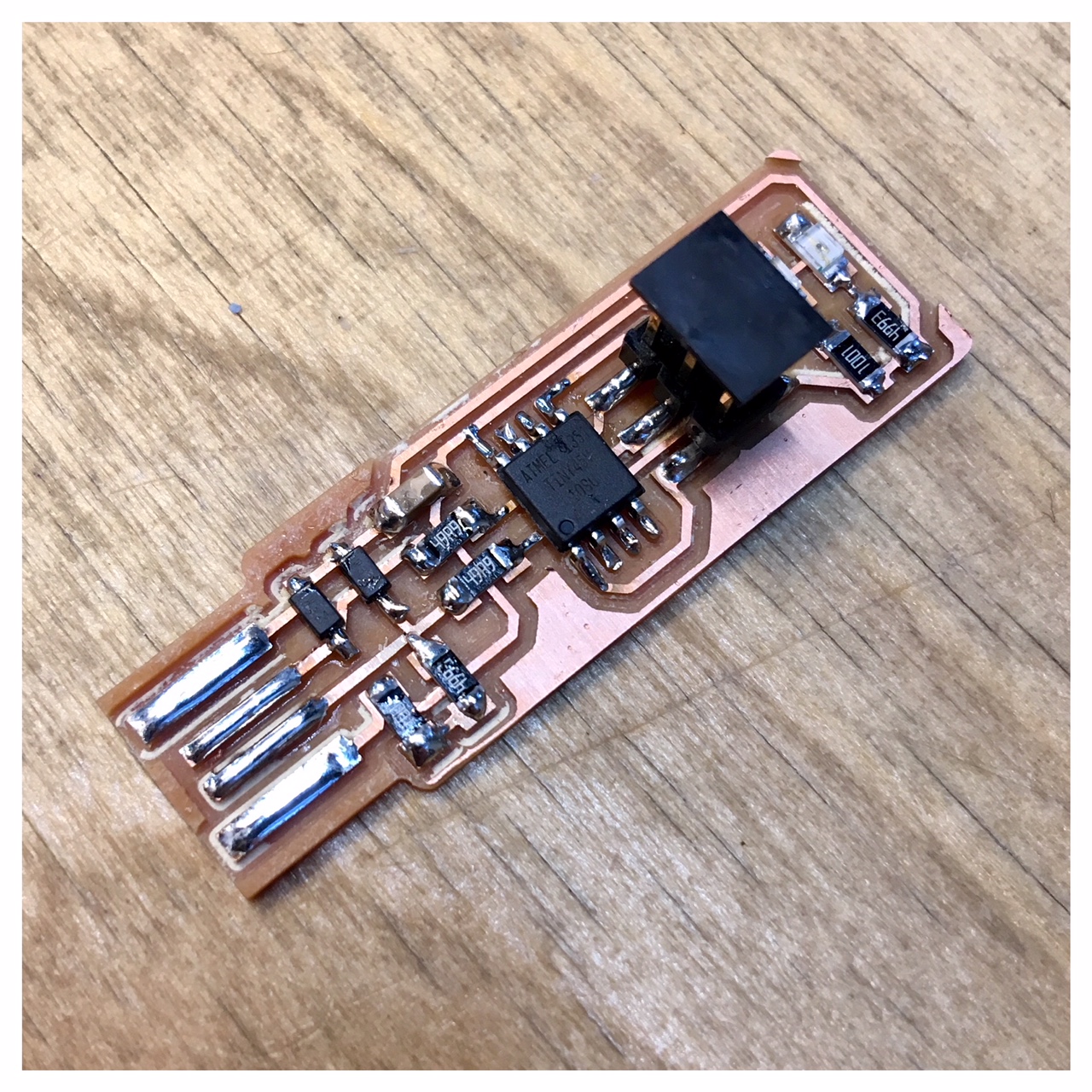
For my FabISP I needed the comonents listet underneath. Initially I had made a version of the ISP (the Andy version) but I found that we where missing some components in our FabLab. They were ordered home but in order not to get behind in schedule, I made another ISP (the Brian edition). I still want to finish the other edition when there is time. The components listed below are for the Brian edition.-ATtiny45 * 1
-1k ohm resistors * 2
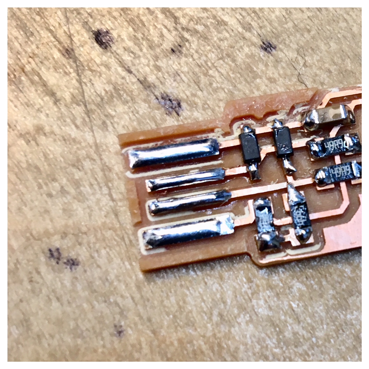
-499 ohm resistors * 2
-49 ohm resistors * 2
-3.3v zener diodes * 2
- red LED * 1
-green LED * 3
-100nF capacitor * 1
-2x3 pin header * 1
Small adjustments of Fab TinyISP
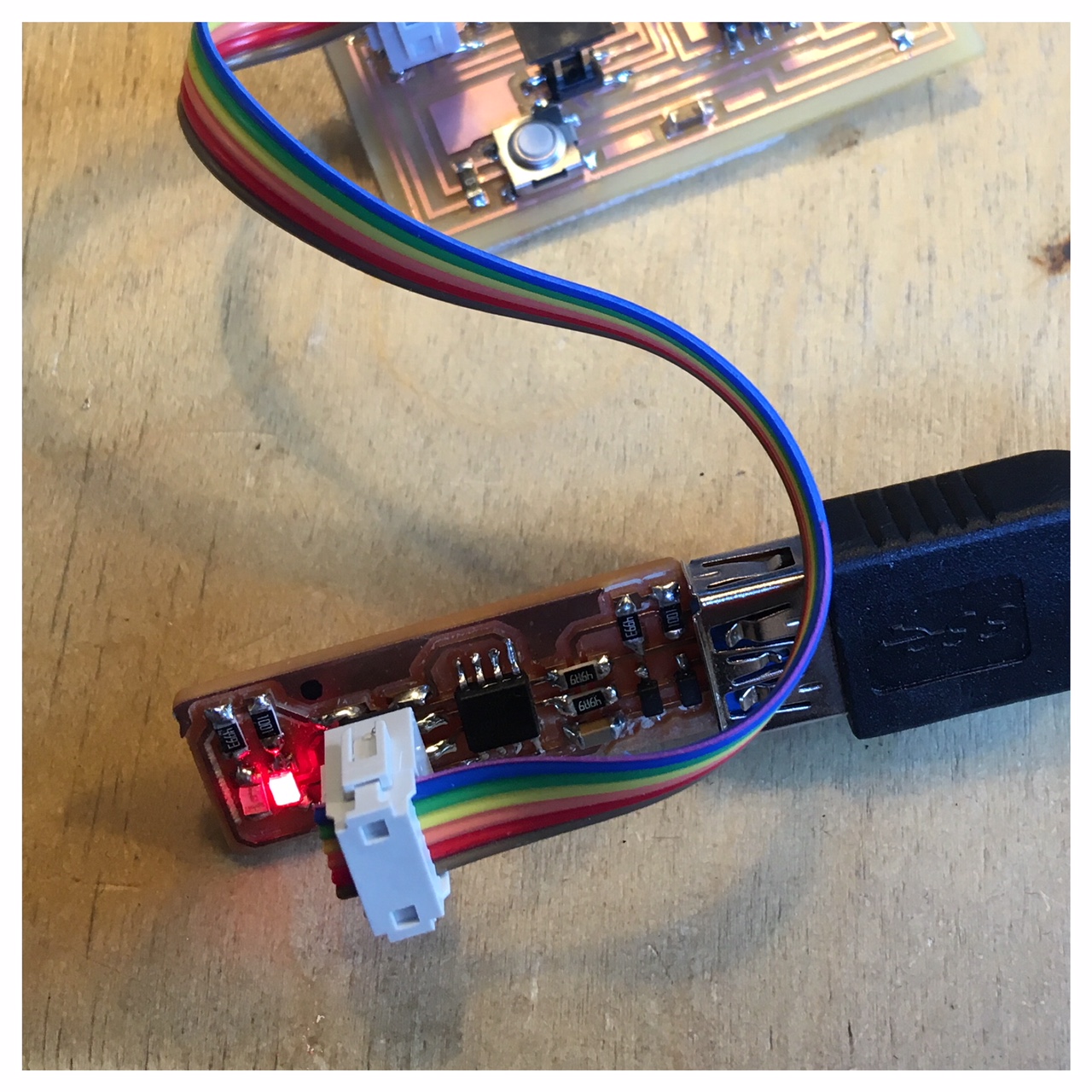
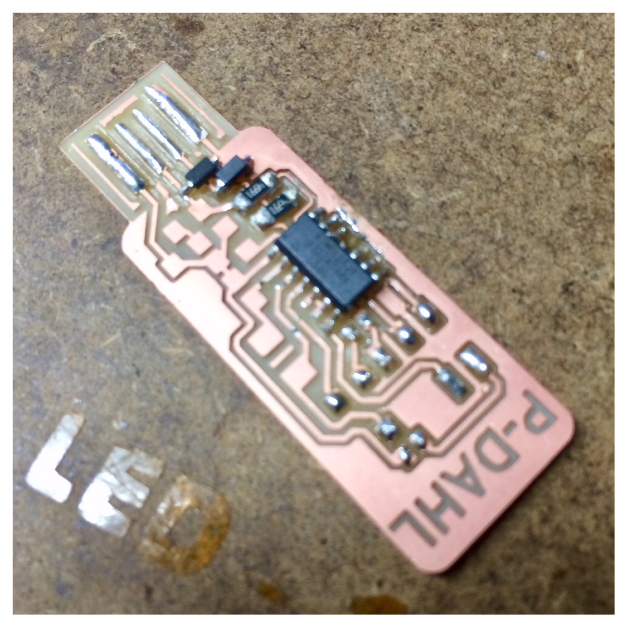
My FabTinyISP ended up slightly thin to work well with my USB ports. To ensure a good USB connection, I recommend to do two samll improvements:
- The first little improvement is to solder a fine line of solder across the pad in one continuous motion to even it out into a smooth layer (Take a look on my image below of the finished programmer for how my USB pad looks).
- Doing the above soldering I found very sufficient most, but I still like to add a little more thickness, so I glued some extra material to the bottom of the PCB. In this case a small scrap of plastic form a lit. I use a tiny drop of glue to affix a small piece to the bottom of the USB connector area.
Programming the FabISP
After finishing assemling, soldering and testing my ISP I followed Brians guide (Building Brians version of the FabTinyISP) to program my FabISP. I used my own computer but at first I had to set up my development environment. To do that, I again followed Brian's instructions for Software Installation for Windows and Using the GNU AVR toolchain on Windows 10. Then I programmed it by using the Avrips mkII programmer ("the blue programmer") Avrips mkII programmer. I followed the steps and it worked perfect after I soldered the little improvement of a fine line of solder across the pads.
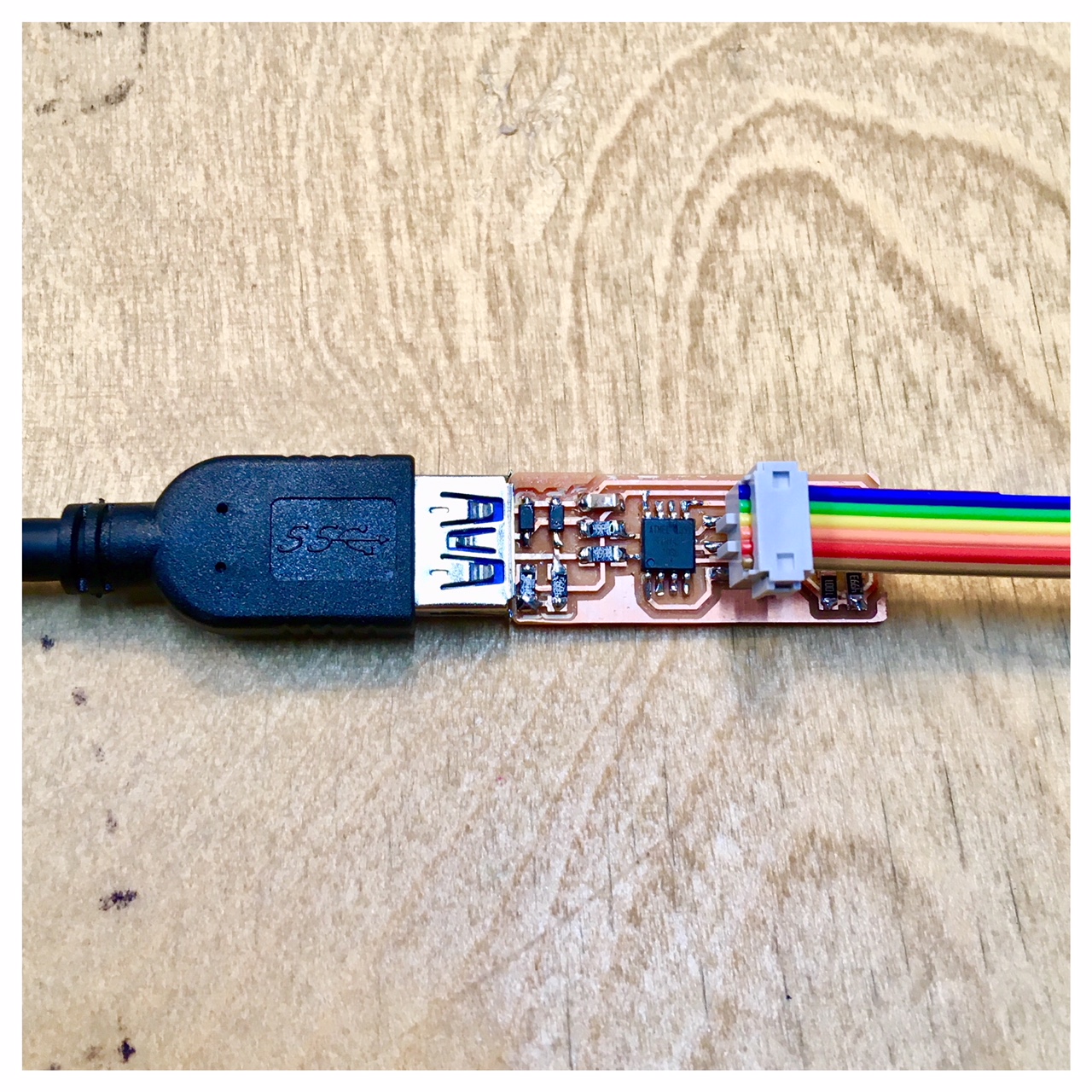
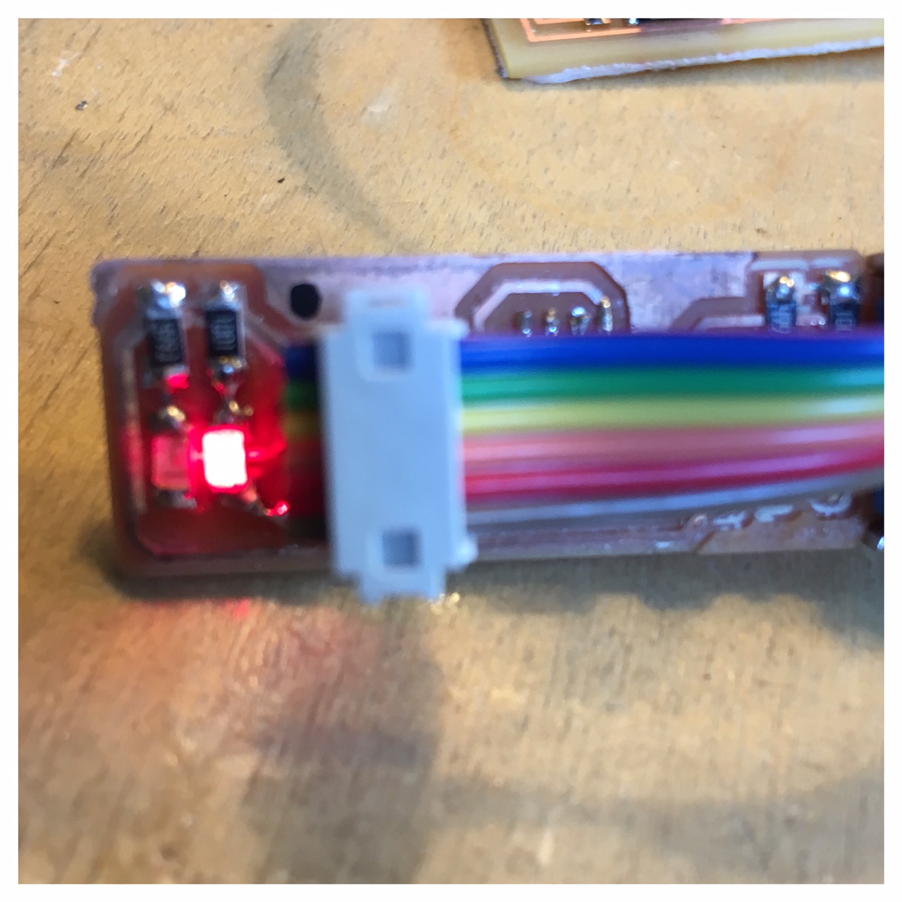
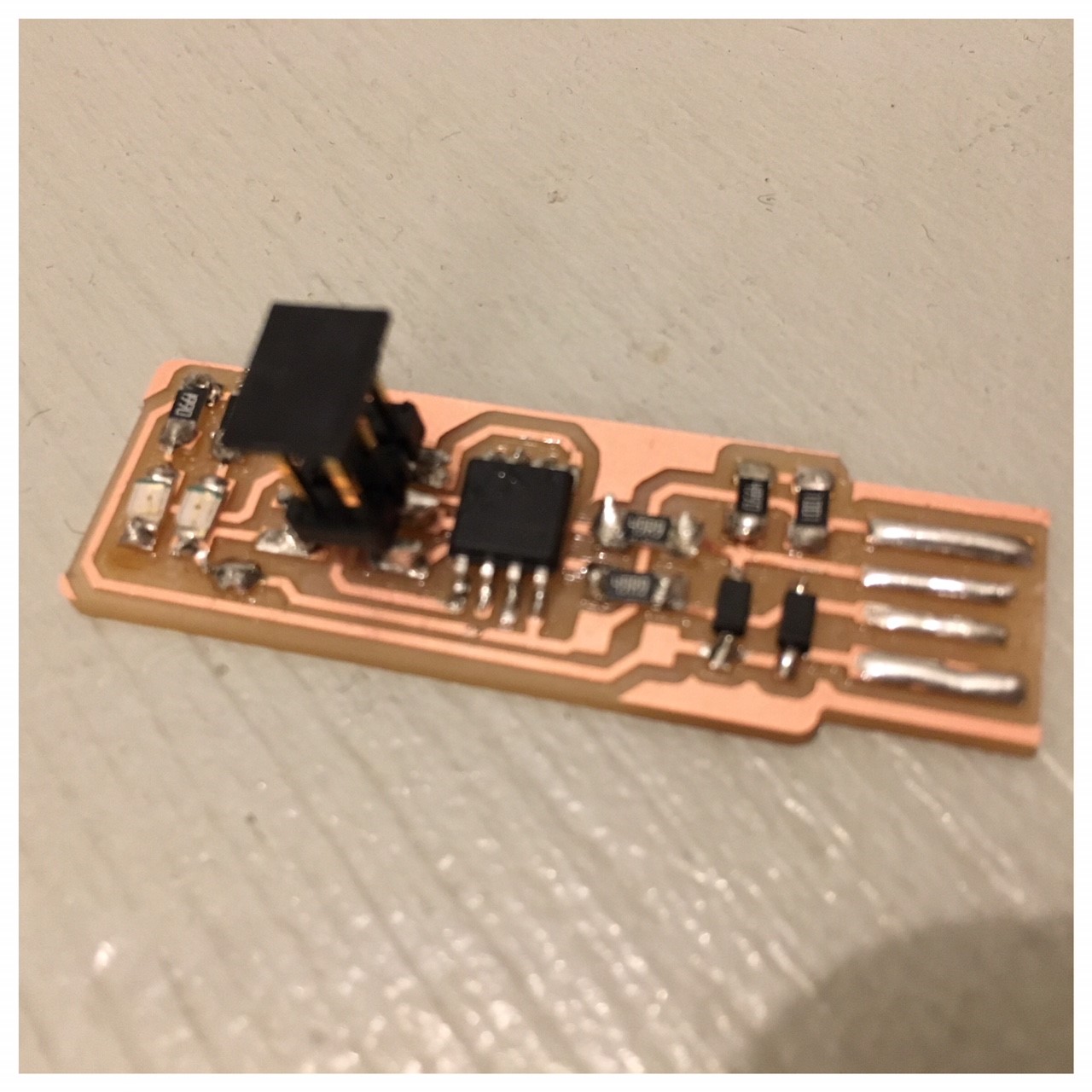
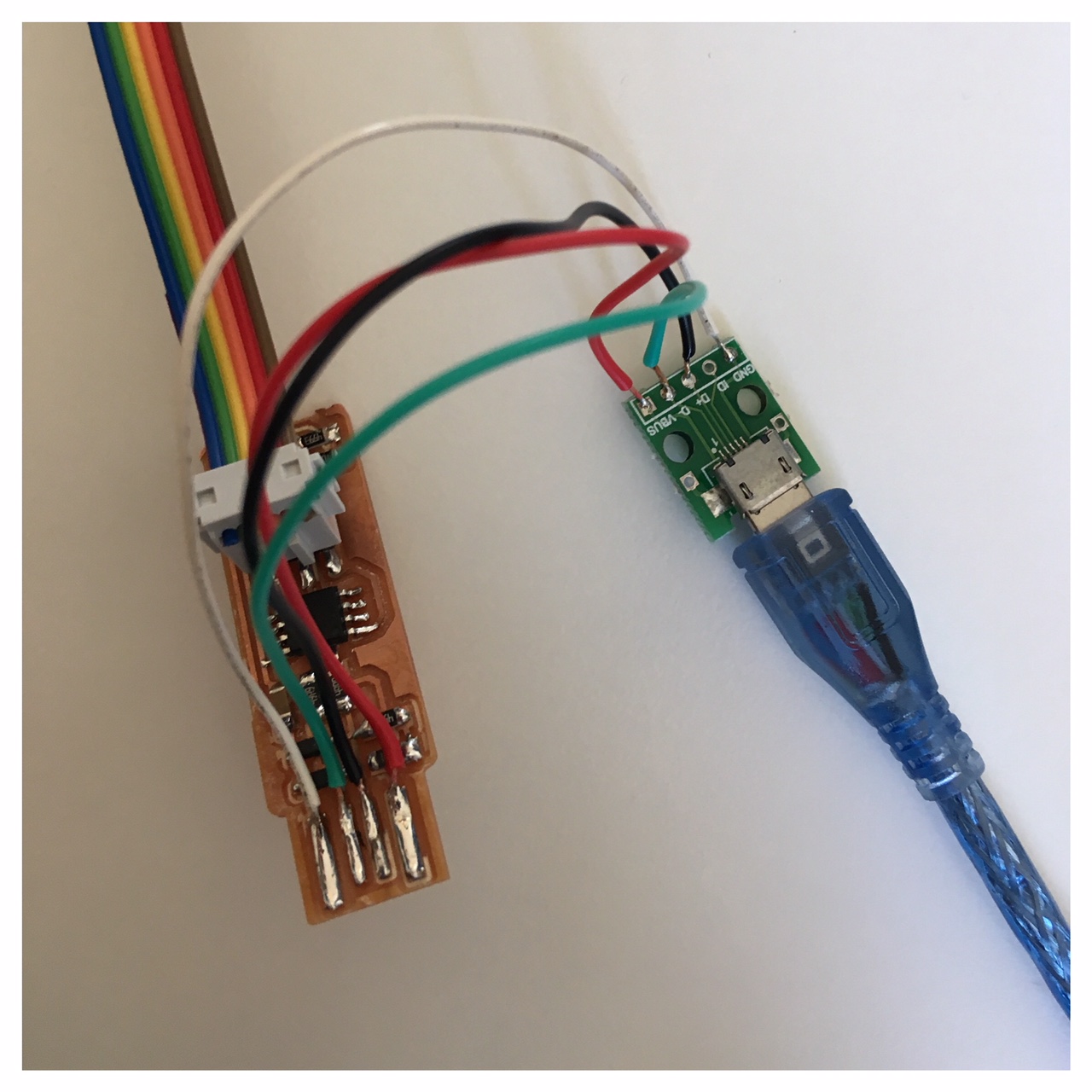
I had some problems with the connection between the USB cable (The female plug) and my ISP. I saw there were a few students around on the Fab Academy pages that had added an extra layer below their ISP to make it thicker. I ended up (like a small experiment) to solder a micro USB plug on my ISP, which made the connection stronger. This worked for med and I think next time I will prefer making a ISP with a micro USB plug on.
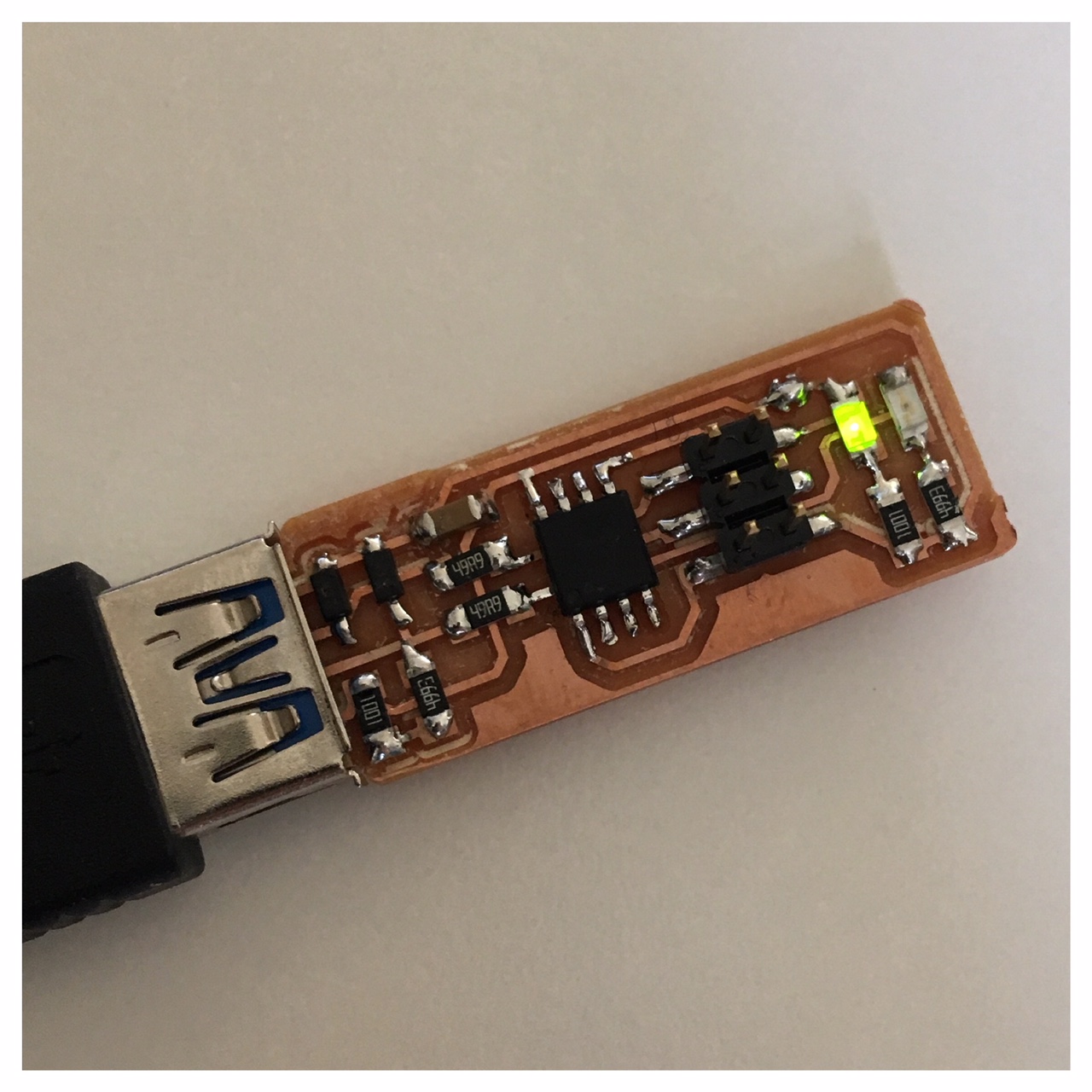
So of course I had soldered the wrong color LED on my ISP (I switched the green and the red one around). Not that it is going to do any difference when I an programming, but I've replaced it with a red LED now, so there's no doubt if a Fab-friend is going to borrow it some day.